As a seasoned control valve supplier, I've witnessed firsthand the importance of proper installation of control valve actuators. A well - installed actuator ensures the efficient and reliable operation of control valves, which are crucial components in various industrial processes. In this blog, I'll guide you through the step - by - step process of installing a control valve actuator.
Pre - installation Preparations
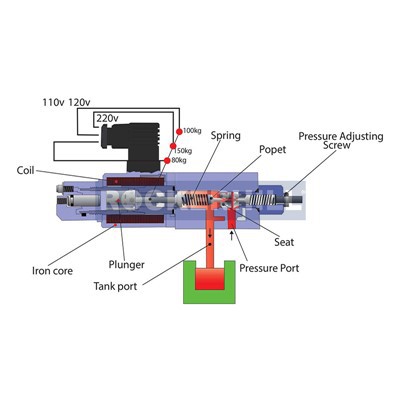
Before you start the installation process, it's essential to make thorough preparations. First, you need to have a clear understanding of the control valve system requirements. This includes knowing the type of control valve you are working with, such as a Pressure Control Valve or a Directional Control Valve. Different types of valves may have specific requirements for actuator installation.
Inspect the actuator and the valve carefully. Check for any visible damage during transportation, such as dents, scratches, or loose parts. Make sure all the necessary components of the actuator, including mounting brackets, fasteners, and electrical or pneumatic connections, are present.
Gather all the tools required for the installation. This typically includes wrenches, screwdrivers, torque wrenches, and possibly a crane or hoist if the actuator is large and heavy. Also, ensure that you have the installation manual for both the actuator and the control valve on hand. The manual will provide detailed instructions and torque specifications that are critical for a proper installation.
Mounting the Actuator
The first physical step in the installation process is to mount the actuator onto the control valve. Most actuators come with a mounting flange that is designed to match the valve's flange. Place the actuator on top of the valve, aligning the bolt holes of the actuator flange with those of the valve flange.
Use the appropriate bolts and nuts to secure the actuator to the valve. It's important to follow the torque specifications provided in the installation manual. Over - tightening the bolts can damage the flanges, while under - tightening can lead to leaks or an unstable connection. For example, if the manual specifies a torque of 50 Nm for a particular size of bolt, use a torque wrench to achieve the exact value.
Once the actuator is bolted onto the valve, check the alignment again. The actuator should be centered and parallel to the valve stem. Any misalignment can cause excessive wear on the valve stem and the actuator components, reducing the lifespan of both the valve and the actuator.
Connecting the Actuator to the Valve Stem
After mounting the actuator, the next step is to connect it to the valve stem. This connection allows the actuator to control the movement of the valve. There are different types of connections, such as direct - mount, yoke - style, or through - shaft connections.
For a direct - mount connection, the actuator is directly attached to the valve stem without any intermediate components. In this case, make sure that the actuator's drive mechanism is properly engaged with the valve stem. Check for any play or looseness in the connection. If there is too much play, it can result in inaccurate valve control.
In a yoke - style connection, a yoke is used to link the actuator to the valve stem. The yoke provides a rigid connection and allows for some adjustment. Install the yoke according to the manufacturer's instructions, and ensure that it is securely fastened to both the actuator and the valve.
For through - shaft connections, the valve stem passes through the actuator. Align the stem correctly and install any necessary locking devices to prevent the stem from slipping out of the actuator during operation.
Electrical or Pneumatic Connections
Depending on the type of actuator, you'll need to make either electrical or pneumatic connections.
Electrical Connections
If it's an electric actuator, start by disconnecting the power source to avoid any electrical hazards. Identify the power supply wires, control signal wires, and any feedback wires. The power supply wires are usually connected to a suitable power source, such as a 24V DC or 110V AC supply, depending on the actuator's requirements.
Connect the control signal wires to the control system. This signal is used to command the actuator to open or close the valve. The feedback wires are used to provide information about the valve's position back to the control system. Make sure all the connections are tight and insulated to prevent short - circuits.
Pneumatic Connections
For pneumatic actuators, connect the air supply lines. Use appropriate fittings and tubing to ensure a leak - free connection. The air supply pressure should be within the range specified by the actuator manufacturer. Install a pressure regulator if necessary to maintain a stable air pressure.
In addition, connect the control air lines. These lines are used to control the movement of the actuator. The control air pressure is adjusted to achieve the desired valve position.
Calibration and Testing
After all the physical and electrical/pneumatic connections are made, it's time to calibrate and test the actuator.
Calibration
Calibration is the process of adjusting the actuator to ensure that it accurately positions the valve according to the control signals. Start by setting the zero and full - scale positions. The zero position corresponds to the fully closed position of the valve, and the full - scale position corresponds to the fully open position.
Use the calibration tools provided with the actuator, such as potentiometers or digital displays, to make the necessary adjustments. For example, if the actuator has a digital display that shows the valve position as a percentage, adjust the settings so that the display reads 0% when the valve is fully closed and 100% when the valve is fully open.
Testing
Once the calibration is complete, perform a series of tests to ensure the proper operation of the actuator. Send a control signal to the actuator to open the valve. Observe the valve's movement and check if it reaches the desired position. Then, send a signal to close the valve and repeat the observation.
Check for any abnormal noises, vibrations, or leaks during the testing. If you notice any issues, such as the valve not opening or closing fully, or if there are air or fluid leaks, troubleshoot the problem immediately. This may involve checking the connections, adjusting the calibration, or replacing faulty components.
Commissioning and Final Checks
After successful testing, the actuator is ready for commissioning. Commissioning involves integrating the actuator - valve system into the overall industrial process.
Check all the safety features of the actuator, such as limit switches and overload protection. These features are designed to prevent damage to the actuator and the valve in case of abnormal operating conditions.
Verify that the control system is receiving accurate feedback from the actuator. This feedback is used to monitor the valve's position and ensure that the process is operating within the desired parameters.
Finally, conduct a final visual inspection of the entire installation. Check for any loose bolts, damaged wires, or other potential issues. Make sure that all the installation documentation, including the calibration records and test results, is properly filed for future reference.


Conclusion
Installing a control valve actuator is a complex but essential process that requires careful planning, precise execution, and thorough testing. As a control valve supplier, I understand the importance of a well - installed actuator in ensuring the reliable and efficient operation of control valves.
If you are in the market for high - quality control valves and actuators, or if you need further assistance with installation, calibration, or maintenance, please don't hesitate to reach out. Our team of experts is ready to provide you with the best solutions tailored to your specific needs. We look forward to discussing your requirements and working with you to achieve optimal performance in your industrial processes.
References
- Manufacturer's installation manuals for control valves and actuators
- Industry standards and guidelines for control valve installation and maintenance